Basics of Database Modeling
This article/tutorial will teach the basis of relational database design and explains how to make a good database design. It is a rather long text, but we advise to read all of it. Designing a database is in fact fairly easy, but there are a few rules to stick to. It is important to know what these rules are, but more importantly is to know why these rules exist, otherwise you will tend to make mistakes!
Standardization makes your data model flexible and that makes working with your data much easier. Please, take the time to learn these rules and apply them! The database used in this article is designed with our database modeling tool DeZign for Databases.
A good database design starts with a list of the data that you want to include in your database and what you want to be able to do with the database later on. This can all be written in your own language, without any SQL. In this stage you must try not to think in tables or columns, but just think: "What do I need to know?" Don't take this too lightly, because if you find out later that you forgot something, usually you need to start all over. Adding things to your database is mostly a lot of work.
Identifying Entities
The types of information that are saved in the database are called 'entities'. These entities exist in four kinds: people, things, events, and locations. Everything you could want to put in a database fits into one of these categories. If the information you want to include doesn't fit into these categories then it is probably not an entity but a property of an entity, an attribute.
To clarify the information given in this article we'll use an example. Imagine that you are creating a website for a shop, what kind of information do you have to deal with? In a shop you sell your products to customers. The "Shop" is a location; "Sale" is an event; "Products" are things; and "Customers" are people. These are all entities that need to be included in your database.
But what other things are happening when selling a product? A customer comes into the shop, approaches the vendor, asks a question and gets an answer. "Vendors" also participate, and because vendors are people, we need a vendors entity.
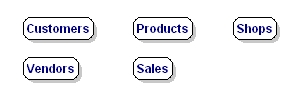
Figure 1: Entities: types of information.
Identifying Relationships
The next step is to determine the relationships between the entities and to determine the cardinality of each relationship. The relationship is the connection between the entities, just like in the real world: what does one entity do with the other, how do they relate to each other? For example, customers buy products, products are sold to customers, a sale comprises products, a sale happens in a shop.
The cardinality shows how much of one side of the relationship belongs to how much of the other side of the relationship. First, you need to state for each relationship, how much of one side belongs to exactly 1 of the other side. For example: How many customers belong to 1 sale?; How many sales belong to 1 customer?; How many sales take place in 1 shop?
You'll get a list like this: (please note that 'product' represents a type of product, not an occurance of a product)
- Customers --> Sales; 1 customer can buy something several times
- Sales --> Customers; 1 sale is always made by 1 customer at the time
- Customers --> Products; 1 customer can buy multiple products
- Products --> Customers; 1 product can be purchased by multiple customers
- Customers --> Shops; 1 customer can purchase in multiple shops
- Shops --> Customers, 1 shop can receive multiple customers
- Shops --> Products; in 1 shop there are multiple products
- Products --> Shops; 1 product (type) can be sold in multiple shops
- Shops --> Sales; in 1 shop multiple sales can me made
- Sales --> Shops; 1 sale can only be made in 1 shop at the time
- Products --> Sales; 1 product (type) can be purchased in multiple sales
- Sales --> Products; 1 sale can exist out of multiple products
Did we mention all relationships? There are four entities and each entity has a relationship with every other entity, so each entity must have three relationships, and also appear on the left end of the relationship three times. Above, 12 relationships were mentioned, which is 4*3, so we can conclude that all relationships were mentioned.
Now we'll put the data together to find the cardinality of the whole relationship. In order to do this, we'll draft the cardinalities per relationship. To make this easy to do, we'll adjust the notation a bit, by noting the 'backward'-relationship the other way around:
- Customers --> Sales; 1 customer can buy something several times
- Sales --> Customers; 1 sale is always made by 1 customer at the time
The second relationship we will turn around so it has the same entity order as the first. Please notice the arrow that is now faced the other way!
- Customers <-- Sales; 1 sale is always made by 1 customer at the time
Cardinality exists in four types: one-to-one, one-to-many, many-to-one, and many-to-many. In a database design this is indicated as: 1:1, 1:N, M:1, and M:N. To find the right indication just leave the '1'. If there is a 'many' on the left side, this will be indicated with 'M', if there is a 'many' on the right side it is indicated with 'N'.
- Customers --> Sales; 1 customer can buy something several times; 1:N.
- Customers <-- Sales; 1 sale is always made by 1 customer at the time; 1:1.
The true cardinality can be calculated through assigning the biggest values for left and right, for which 'N' or 'M' are greater than '1'. In thisexample, in both cases there is a '1' on the left side. On the right side, there is a 'N' and a '1', the 'N' is the biggest value. The total cardinality is therefore '1:N'. A customer can make multiple 'sales', but each 'sale' has just one customer.
If we do this for the other relationships too, we'll get:
- Customers --> Sales; --> 1:N
- Customers --> Products; --> M:N
- Customers --> Shops; --> M:N
- Sales --> Products; --> M:N
- Shops --> Sales; --> 1:N
- Shops --> Products; --> M:N
So, we have two '1-to-many' relationships, and four 'many-to-many' relationships.
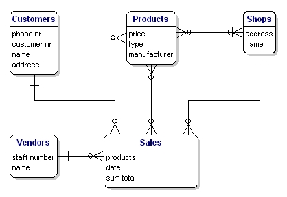
Figure 2: Relationships between the entities.
Between the entities there may be a mutual dependency. This means that the one item cannot exist if the other item does not exist. For example, there cannot be a sale if there are no customers, and there cannot be a sale if there are no products.
The relationships Sales --> Customers, and Sales --> Products are mandatory, but the other way around this is not the case. A customer can exist without sale, and also a product can exist without sale. This is of importance for the next step.
Recursive Relationships
Sometimes an entity refers back to itself. For example, think of a work hierarchy: an employee has a boss; and the bosschef is an employee too. The attribute 'boss' of the entity 'employees' refers back to the entity 'employees'.
In an ERD (see next chapter) this type of relationship is a line that goes out of the entity and returns with a nice loop to the same entity.
Redundant Relationships
Sometimes in your model you will get a 'redundant relationship'. These are relationships that are already indicated by other relationships, although not directly.
In the case of our example there is a direct relationships between customers and products. But there are also relationships from customers to sales and from sales to products, so indirectly there already is a relationship between customers and products through sales. The relationship 'Customers <----> Products' is made twice, and one of them is therefore redundant. In this case, products are only purchased through a sale, so the relationships 'Customers <----> Products' can be deleted. The model will then look like this:
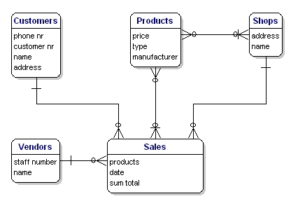
Figure 3: Relationships between the entities.
Solving Many-to-Many Relationships
Many-to-many relationships (M:N) are not directly possible in a database. What a M:N relationship says is that a number of records from one table belongs to a number of records from another table. Somewhere you need to save which records these are and the solution is to split the relationship up in two one-to-many relationships.
This can be done by creating a new entity that is in between the related entities. In our example, there is a many-to-many relationship between sales and products. This can be solved by creating a new entity: sales-products. This entity has a many-to-one relationship with Sales, and a many-to-one relationship with Products. In logical models this is called an associative entity and in physical database terms this is called a link table, intersection table or junction table.

Figure 4a: Many to many relationship.

Figure 4b: Many to many relationship implementation via associative entity.
In the example there are two many-to-many relationships that need to be solved: 'Products <----> Sales', and 'Products <----> Shops'. For both situations there needs to be created a new entity, but what is that entity?
For the Products <----> Sales relationship, every sale includes more products. The relationship shows the content of the sale. In other words, it gives details about the sale. So the entity is called 'Sales details'. You could also name it 'sold products'.
The Products <----> Shops relationship shows which products are available in which the shops, also known as 'stock'. Our model would now look like this:
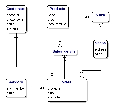
Figure 5: Model with link tables Stock and Sales_details.
Start Designing A Database Today
Identifying Attributes
The data elements that you want to save for each entity are called 'attributes'.
About the products that you sell, you want to know, for example, what the price is, what the name of the manufacturer is, and what the type number is. About the customers you know their customer number, their name, and address. About the shops you know the location code, the name, the address. Of the sales you know when they happened, in which shop, what products were sold, and the sum total of the sale. Of the vendor you know his staff number, name, and address. What will be included precisely is not of importance yet; it is still only about what you want to save.
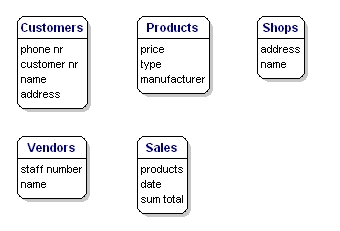
Figure 6: Entities with attributes.
Derived Data
Derived data is data that is derived from the other data that you have already saved. In this case the 'sum total' is a classical case of derived data. You know exactly what has been sold and what each product costs, so you can always calculate how much the sum total of the sales is. So really it is not necessary to save the sum total.
So why is it saved here? Well, because it is a sale, and the price of the product can vary over time. A product can be priced at 10 euros today and at 8 euros next month, and for your administration you need to know what it cost at the time of the sale, and the easiest way to do this is to save it here. There are a lot of more elegant ways, but they are too profound for this article.
Presenting Entities and Relationships: Entity Relationship Diagram (ERD)
The Entity Relationship Diagram (ERD) gives a graphical overview of the database. There are several styles and types of ER Diagrams. A much-used notation is the 'crowfeet' notation, where entities are represented as rectangles and the relationships between the entities are represented as lines between the entities. The signs at the end of the lines indicate the type of relationship. The side of the relationship that is mandatory for the other to exist will be indicated through a dash on the line. Not mandatory entities are indicated through a circle. "Many" is indicated through a 'crowfeet'; the relationship-line splits up in three lines.
In this article we make use of DeZign for Databases to model and present our database.
A 1:1 mandatory relationship is represented as follows:
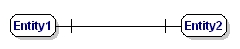
Figure 7: Mandatory one to one relationship.
A 1:N mandatory relationship:
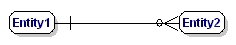
Figure 8: Mandatory one to many relationship.
A M:N relationship is:
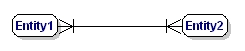
Figure 9: Mandatory many to many relationship.
The model of our example will look like this:
Figure 10: Model with relationships.
Assigning Keys
Primary Keys
A primary key (PK) is one or more data attributes that uniquely identify an entity. A key that consists of two or more attributes is called a composite key. All attributes part of a primary key must have a value in every record (which cannot be left empty) and the combination of the values within these attributes must be unique in the table.
In the example there are a few obvious candidates for the primary key. Customers all have a customer number, products all have a unique product number and the sales have a sales number. Each of these data is unique and each record will contain a value, so these attributes can be a primary key. Often an integer column is used for the primary key so a record can be easily found through its number.
Link-entities usually refer to the primary key attributes of the entities that they link. The primary key of a link-entity is usually a collection of these reference-attributes. For example in the Sales_details entity we could use the combination of the PK's of the sales and products entities as the PK of Sales_details. In this way we enforce that the same product (type) can only be used once in the same sale. Multiple items of the same product type in a sale must be indicated by the quantity.
In the ERD the primary key attributes are indicated by the text 'PK' behind the name of the attribute. In the example only the entity 'shop' does not have an obvious candidate for the PK, so we will introduce a new attribute for that entity: shopnr.
Foreign Keys
The Foreign Key (FK) in an entity is the reference to the primary key of another entity. In the ERD that attribute will be indicated with 'FK' behind its name. The foreign key of an entity can also be part of the primary key, in that case the attribute will be indicated with 'PF' behind its name. This is usually the case with the link-entities, because you usually link two instances only once together (with 1 sale only 1 product type is sold 1 time).
If we put all link-entities, PK's and FK's into the ERD, we get the model as shown below. Please note that the attribute 'products' is no longer necessary in 'Sales', because 'sold products' is now included in the link-table. In the link-table another field was added, 'quantity', that indicates how many products were sold. The quantity field was also added in the stock-table, to indicate how many products are still in store.
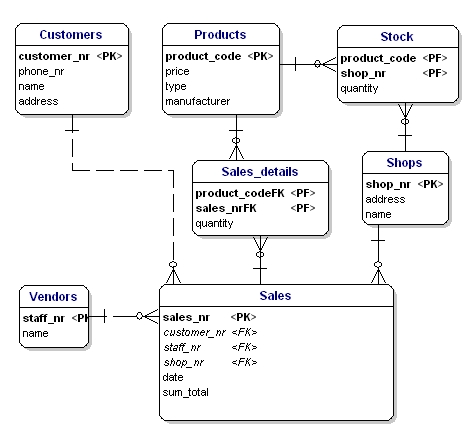
Figure 11: Primary keys and foreign keys.
Defining the Attribute's Data Type
Now it is time to figure out which data types need to be used for the attributes. There are a lot of different data types. A few are standardized, but many databases have their own data types that all have their own advantages. Some databases offerthe possibility to define your own data types, in case the standard types cannot do the things you need.
The standard data types that every database knows, and are most-used, are: CHAR, VARCHAR, TEXT, FLOAT, DOUBLE, and INT.
Text:
- CHAR(length) - includes text (characters, numbers, punctuations...). CHAR has as characteristic that it always saves a fixed amount of positions. If you define a CHAR(10) you can save up to ten positions maximum, but if you only use two positions the database will still save 10 positions. The remaining eight positions will be filled by spaces.
- VARCHAR(length) - includes text (characters, numbers, punctuation...). VARCHAR is the same as CHAR, the difference is that VARCHAR only takes as much space as necessary.
- TEXT - can contain large amounts of text. Depending on the type of database this can add up to gigabytes.
Numbers:
- INT - contains a positive or negative whole number. A lot of databases have variations of the INT, such as TINYINT, SMALLINT, MEDIUMINT, BIGINT, INT2, INT4, INT8. These variations differ from the INT only in the size of the figure that fits into it. A regular INT is 4 bytes (INT4) and fits figures from -2147483647 to +2147483646, or if you define it as UNSIGNED from 0 to 4294967296. The INT8, or BIGINT, can get even bigger in size, from 0 to 18446744073709551616, but takes up to 8 bytes of diskspace, even if there is just a small number in it.
- FLOAT, DOUBLE - The same idea as INT, but can also store floating point numbers. . Do note that this does not always work perfectly. For instance in MySQL calculating with these floating point numbers is not perfect, (1/3)*3 will result with MySQL's floats in 0.9999999, not 1.
Other types:
- BLOB - for binary data such as files.
- INET - for IP addresses. Also useable for netmasks.
For our example the data types are as follows:
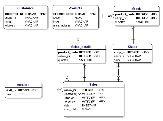
Figure 12: Data model displaying data types.
Normalization
Normalization makes your data model flexible and reliable. It does generate some overhead because you usually get more tables, but it enables you to do many things with your data model without having to adjust it. Learn more about database normalization principles in our database normalization guide.
Normalization, the First Form
The first form of normalization states that there may be no repeating groups of columns in an entity. We could have created an entity 'sales' with attributes for each of the products that were bought. This would look like this:
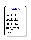
Figure 13: Not in 1st normal form.
What is wrong about this is that now only 3 products can be sold. If you would have to sell 4 products then you would have to start a second sale or adjust your data model by adding 'product4' attributes. Both solutions are unwanted. In these cases you should always create a new entity that you link to the old one via a one-to-many relationship.
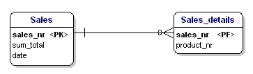
Figure 14: In accordance with 1st normal form.
Normalization, the Second Form
The second form of normalization states that all attributes of an entity should be fully dependent on the whole primary key. This means that each attribute of an entity can only be identified through the whole primary key. Suppose we had the date in the Sales_details entity:
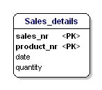
Figure 15: Not in 2nd normal form.
This entity is not according the second normalization form, because in order to be able to look up the date of a sale, I do not have to know what is sold (productnr), the only thing I need to know is the sales number. This was solved by splitting up the tables into the sales and the Sales_details table:

Figure 16: In accordance with 2nd normal form.
Now each attribute of the entities is dependent on the whole PK of the entity. The date is dependent on the sales number, and the quantity is dependent on the sales number and the sold product.
Normalization, the Third Form
The third form of normalization states that all attributes need to be directly dependent on the primary key, and not on other attributes. This seems to be what the second form of normalization states, but in the second form is actually stated the opposite. In the second form of normalization you point out attributes through the PK, in the third form of normalization every attribute needs to be dependent on the PK, and nothing else.
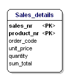
Figure 17: Not in 3rd normal form.
In this case the price of a loose product is dependent on the ordering number, and the ordering number is dependent on the product number and the sales number. This is not according to the third form of normalization. Again, splitting up the tables solves this.
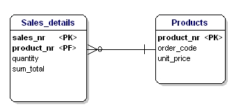
Figure 18: In accordance with 3rd normal form.
Normalization, More Forms
There are more normalization forms than the three forms mentioned above, but those are not of great interest for the average user. These other forms are highly specialized for certain applications. If you stick to the design rules and the normalization mentioned in this article, you will create a design that works great for most applications.
Normalized Data Model
If you apply the normalization rules, you will find that the 'manufacturer' in the product table should also be a separate table:

Figure 19: Data model in accordance with 1st, 2nd and 3d normal form.
Glossary
Attributes - detailed data about an entity, such as price, length, name
Cardinality - the relationship between two entities, in figures. For example, a person can place multiple orders.
Entities - abstract data that you save in a database. For example: customers, products.
Foreign key (FK) - a referral to the Primary Key of another table. Foreign Key-columns can only contain values that exist in the Primary Key column that they refer to.
Key - a key is used to point out records. The most well-known key is the Primary Key (see Primary Key).
Normalization - A flexible data model needs to follow certain rules. Applying these rules is called normalizing.
Primary key - one or more columns within a table that together form a unique combination of values by which each record can be pointed out separately. For example: customer numbers, or the serial number of a product.
Get Started Today
And see why tens of thousands of data modelers worldwide choose DeZign for Databases.
Try Out DeZign for Databases (14 days free trial)Resources
Learn- Database normalization: Learn how to normalize a data model (1NF, 2NF, 3NF). the entity boxes on your diagram.